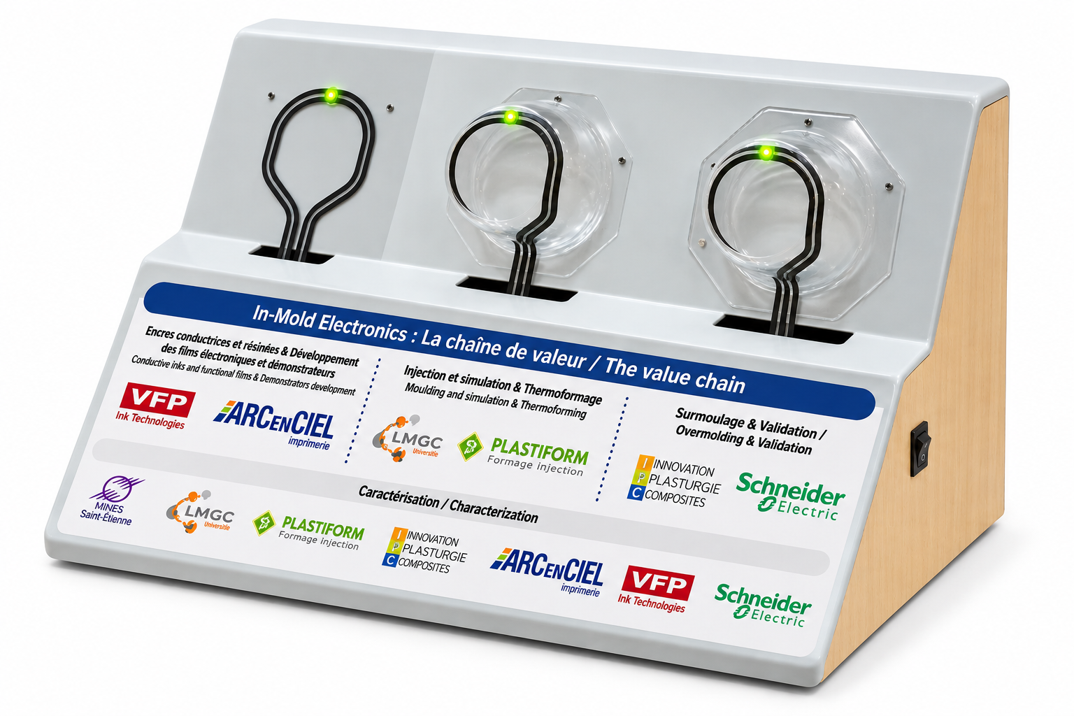
An in-mold electronics (IME) ink is a functional ink, most often a silver-based conductive ink, screen printed onto a flat plastic film that is then thermoformed and overmolded by injection. It must therefore stay conductive after stretching, adhere to the film throughout the process and withstand the flow of injected resin. This ink is what turns a decorated plastic part into an electronic interface: conductive tracks, capacitive touch sensors, integrated lighting.
Plastronics, IME and structural electronics: what are we talking about?
Plastronics covers the technologies that integrate electronic functions directly into plastic parts. It includes several routes: three-dimensional molded interconnect devices (3D-MID), often produced by laser direct structuring (LDS), direct printing onto 3D parts, and in-mold electronics, often grouped under the broader heading of structural electronics. IME has one feature that makes it particularly accessible to printers: everything happens on a flat film. The electronic functions are printed like a decoration, with the same screen printing tools, then the film takes its final shape and becomes the skin of the injected part. The result is a continuous surface with no mechanical buttons or wiring harness, thinner and lighter than a conventional assembly of housing, circuit board and connectors. Typical uses include automotive interior controls, appliance control panels and industrial human machine interfaces.
The IME process, from printed film to molded part
An IME project generally follows five steps. First, flat printing: decorative layers, conductive tracks, dielectric layers and, where needed, carbon contacts are screen printed one after another onto a formable film, often polycarbonate, each layer being dried or cured before the next. Second, component placement: LEDs, integrated circuits or connectors are mounted on the tracks, usually with conductive adhesives. Third, thermoforming heats the film and gives it its three-dimensional shape. The part is then trimmed and placed in an injection mold, where a thermoplastic resin is injected behind the film. The circuit ends up encapsulated between the film and the injected material, protected for the lifetime of the product.
What an in-mold electronics ink must withstand
The process, more than the application, sets the ink specification. Each step imposes a different constraint.
- Stretching during forming: in radii and corners, the film elongates significantly in places. A conventional conductive track cracks and loses electrical continuity; an ink designed for IME, usually called a thermoformable or stretchable conductive ink, must stretch with the film and keep a usable resistance after deformation.
- Resistance drift: even without breaking, a track's resistance increases when it is stretched. Circuit design must account for this change, measured on formed test pieces and not only on flat ones.
- Thermal budget: drying, curing and forming must remain compatible with the film, without distorting it before it is shaped.
- Adhesion across the stack: the ink must hold on the film, on the decorative layers and under the layers that cover it, then stay bonded to the injected resin.
- Resistance to injection: the injected material arrives hot and under pressure. Near the gate, it can tear away or displace a poorly anchored layer; this is ink wash-out, which formulation and part design must prevent.
A functional stack, not a single ink
An IME part is never printed with one ink alone. Silver provides the tracks and the electrodes of capacitive sensors; dielectric inks and varnishes insulate track crossovers; carbon inks can protect contacts or create resistive elements. All these layers must be chemically compatible with each other and with the decorative inks, then pass through forming and injection together. This is where working with a formulator that masters several layers of the stack makes the difference: for example, the data sheets of the ECV003 and ECV004 UV dielectric varnishes state chemical compatibility with the Silver Electron range. VFP Ink Technologies formulates both screen printing inks for decoration and functional inks for printed electronics, which makes it possible to study the stack as a whole rather than layer by layer.
Qualifying an IME ink on your process
No data sheet value on its own guarantees a working part. How an ink behaves in IME depends on the chosen film, the deposited thickness, the drying cycle, the actual stretch ratio in the forming tool and the injection parameters. Serious projects therefore start with trials on the customer's own configuration: resistance measurements before and after forming, adhesion checks, then validation on an injected part. In the VFP range, the data sheet of SILVER ELECTRON STRETCHABLE, a stretchable silver conductive ink, lists in-mold electronics among its applications, with a resistivity below 15 mΩ/sq/mil (3.8×10⁻⁷ Ω·m) and listed substrates including polycarbonate, PET and polyurethane. Its suitability for your process is confirmed in trials. VFP supports reference selection, trials and qualification, and formulates inks that are not classified as carcinogenic, mutagenic or toxic to reproduction (non-CMR), depending on the reference.
Frequently asked questions
What is plastronics?
Plastronics groups the technologies that integrate electronics directly into a plastic part instead of housing a separate circuit board inside it. In-mold electronics is one branch: the functions are printed on a film that is thermoformed and then overmolded by injection.
Is a standard silver conductive ink suitable for IME?
Not necessarily. A silver ink designed for flat circuits can crack when the film is stretched during forming. IME requires an ink that follows the deformation of the film and keeps a usable resistance, which is verified in trials.
Which films are used in in-mold electronics?
Polycarbonate is the most common film, as it thermoforms well and bonds with injected resins. Other formable films are used depending on the part. Compatibility between ink and film is validated reference by reference.
Related resources
Explore the ranges: Conductive inks for printed electronics, Silver conductive inks for printed electronic circuits. Product sheet: SILVER ELECTRON STRETCHABLE. Printed electronics. Discuss your project.